Welded joints
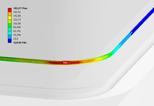
Traditionally, welded joints are calculated and evaluated using analytically determined nominal stresses. The calculation of weld seams through FEM enables a significantly higher quality due to the use of local stresses.
Usually, weld seams are not displayed in 3D CAD models. Depending on the complexity of the assembly, the time required for modeling would simply be too long. Even if the seam geometry were available in CAD, it would not be possible to achieve a sufficiently high resolution in meshing due to the resulting model size. Within the preparation of the 3D FEM model, the welded joints can be mapped using corresponding contact formulations. It is important that the degrees of stiffness are displayed realistically. As a result, in addition to the local distribution of the stresses for the dimensioning of the non-welded areas, the forces and moments transmitted in the respective contact can now be read out for the welded joints, thus providing a strength verification according to the nominal stress concept.
BENEFIT FROM OUR EXPERIENCE.
WE LOOK FORWARD TO HEARING FROM YOU.
We have been working with the FKM guideline since 1996 and we create static strength verifications, fatigue tests and weld seam tests with local stresses. In addition to the FKM guideline in mechanical engineering, we also apply other regulations:
Machine, plant and steel construction (e.g. Eurocode, DIN 18800, DIN13155)
AD2000 and ASME
Machine elements (e.g. screws VDI2230)
Power engineering plants (KTA)
Rail vehicles (e.g. UIC, DIN12663)
Driver cabins (ROPS)
Assessments according to customer specifications